Sailing Back To Zingara’s Roots
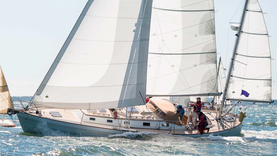
Since we took ownership of our sweet little Spirit of Tradition yacht, Zingara has brought much joy to us on the water – the boat is great fit to our seasonal agenda. Hosting clients aboard is a great way to build relations and Zingara is a solid and beautiful platform. We enjoy a few regatta events each year and this gives the SWD design team something to chew on; the company team-building is good fun and something to look forward to. And, owning a boat as business partners is a helpful way to manage time aboard during busy seasonal schedules, yet this allows us a welcome distraction of sailing together — it’s fun and rewarding working as a short-handed duo to manage the boat underway.
The access to sailing life Zingara brings our families and friends is comfortable at this manageable size.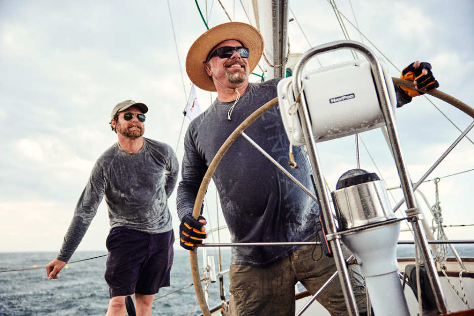
With all that, Zingara has caused deeper reflections for us as we get a handle on the stewardship of our beloved yacht. Now, after 20+ years in service, many things are ready for updates. Looking forward, it’s important that we organize things for the way we want to sail and operate. For us, this means modernizing performance and comfort—these priorities will transform the sailing platform to bring us long-term enjoyment with a meaningful reboot.
There are deliberate updates to the way we will operate Zingara. These updates will also enhance the way in which the yacht remains relevant to Spirit of Tradition sailing. The modernizing effort is an exercise in optimizing the sailing platform by designing a modern rig and sail plan, and working to improve focused operational parameters.
Zingara offers us an opportunity to install our sailing templates— implementing our philosophy for planning of the rig and sails. The tweaks and mods we make to Zingara reflect many ideas tested and built for SWD clients over the years. We’re bringing to life the very stuff we’ve written about and we’re illustrating the best of our skills and value engineering— a true grass-roots Spirit of Tradition program.
Rig & Sail Plan
Perhaps the most interesting evolution of this boat is in the designs of 3 very different sail plans over the past 3 decades. When Bill Peterson penned the first draft plans of Zingara, in 1989, he showed a unique and very complex rig design and sail arrangement.
Seen in the first schematic, the broad elliptical shape at top of main and main mast is combined with a smaller working jib. The trick here was that Bill’s rig plan is a free-standing, articulating system–the jib and headstay was to be set on a radiused track and was to be rotated with the mast for adjustment to the breeze in certain conditions and angles. Not exactly conventional; not exactly simple.
Though the information in the short list of plans we acquired with the boat in 2000 was barely adequate for the most experienced boatbuilder, we know the mast was conceived as a free-standing rotating mast with long chord and airfoil section, supporting the luff of the conventional Dacron mainsail; definitely cutting edge for the late ‘80’s. We also know it must have taken a lot of expertise and leap of faith to complete the construction of the rig. This is likely one of the many reasons this boat never became a reality under the initial design—a brief that’s overly complex in some areas, and not complex enough in others, to achieve such an ambitious single-handed agenda including the original goal of sailing in the BOC race.
The rig was based on assembling a carbon fiber foil-shaped tube that sleeves over an internal carbon “spar” and large bronze pintle foundation to support the mast and deliver the cantilever loads down into the hull structure. This pintle arrangement would allow rotation of the foil tube, resting on a simple set of thrust bearings inside the mast foil. As mentioned, the heads’l and headstay were imagined to swing a radius with this rotating movement, which would provide ability to adjust the entire sailplan with the center of rotation at the mast and radiating to the arced track on the foredeck that mounted a headstay on a car. This functionality may have led to all kinds of trimming capability (we’ll never know) but most certainly would come with some great cost and complexity—expensive headaches, as we say in the trade. To our knowledge the rig was actually engineered and constructed in Rhode Island but never saw the light of day on the boat.
The boat showed up at Brooklin Boat Yard in 1999 after a decade of dysfunctional ownership and incomplete construction — unrealized and unproven, about 60% completed. We imagine whoever intended to sail the boat around the world (in the BOC racing of the time) may have been forever lucky not to have been caught in the Southern ocean in such a setup. The new owner who brought the boat to us at Brooklin Boat Yard was all-in to scrap the design direction Peterson first took and employed us to reimagine Zingara as a cruising yacht; that process began by demolition of the as-built details and striking out with only her bare hull and deck.
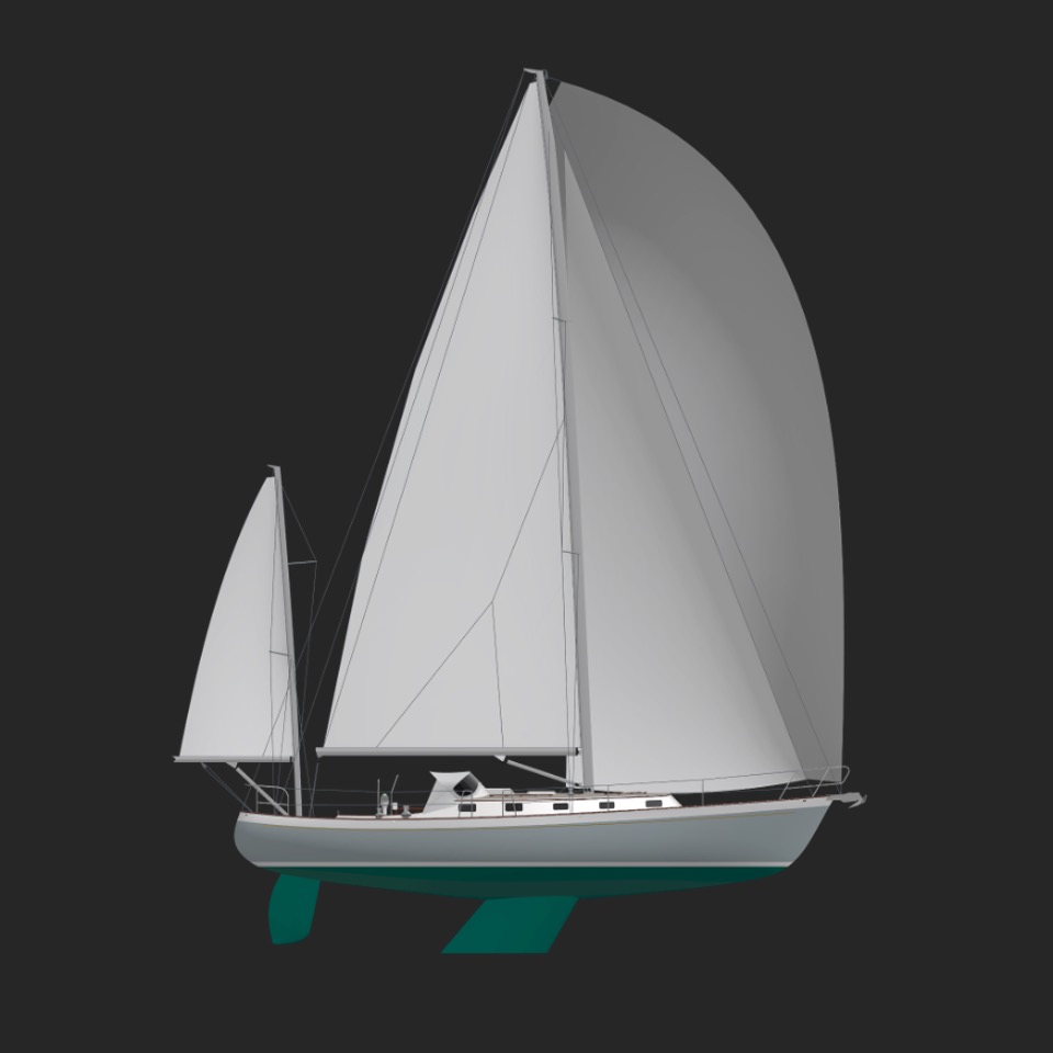
Centered in that design brief was a yawl arrangement for the yacht. As can be seen by the plan, the yawl rig is conservative by its humble sail area. The weight of spars and sails ultimately limited her sail carrying capacity, but our client’s sailing brief of longer offshore journeys under short-handed crew demanded we aim her horsepower on the conservative side.
Also, still wed to tradition and his training of the 60’s-70’s era of sail management, the client wished the rig to carry multiple varying overlapping headsails—an argument against which we’ve been making for two decades. Not only is storage required for all the inventory, the plan demands multiple sheeting solutions on deck and rails to handle trim for each head sail. Additionally, the chainplates are planted well inboard to allow the clew and sheets to clear easily for upwind sheeting of overlapping genoas. This leads to diminishing problems when engineering the spar: when chainplates are pushed inboard to allow close sheeting of overlapping sails, the narrow shroud base has to work harder to keep the mast in column and support the rig properly. This means the chainplates and shrouds are larger and heavier to absorb more load, and the mast tube needs to be larger and heavier to resist buckling and compression loads. All this equates to weight in the air and a higher center of gravity, less stability, less comfort, and less sail-carrying power.
A New Program
Over the winter season, we’ve made some big changes starting with some core priorities which deliver the most bang for the buck:
1) Improve light air sailing.
2) Improve and optimize the sailing platform.
3) Simplify: reduce the amount of clutter on deck.
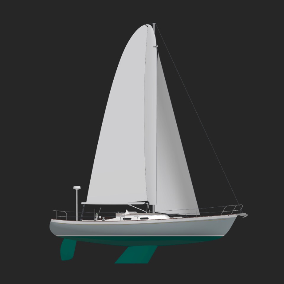
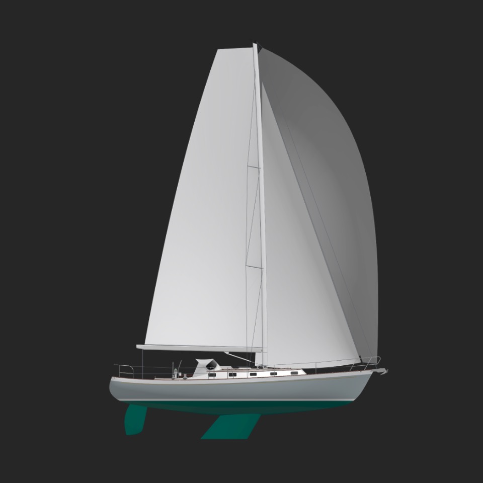
We’ll accomplish this by modifying to a sloop rig arrangement. With the shroud base set as wide as possible to eliminate overlapping sails we’ll reduce all loads on the spars and rigging as much as possible; thereby reducing weight aloft and increase stability. We’ll pack all the power the boat needs for most sailing days in a larger, simpler rig that focuses efficiency in a muscular mainsail. Our stability calculations work out to optimize this situation with an overall increased sail area by 20%. Sounds easy.
In the new plan, note the three basic sails: the large Main, smaller working-Jib, and A-sail. This is all the sail we need for most days. Note how the jib is held to around 105% with the leach and clew tucked as far aft as possible to fit with the spreader geometry. This will drive relocation of the jib track further forward, but will keep a very tight and efficient jib shape that makes tacking and jibing easy.
We’re going with the more efficient square-headed shape in the Mains’l. The design of the rig is important. With spreaders sweeping at approximately 27 degrees and no backstay, we can deploy the deeply roached broad-headed shape without worry. We find it interesting that we’re now bringing the boat full circle to a rig planform more closely aimed at her roots– a sloop with broad headed main and modern sailplan generally aimed at ease and performance.
The aerodynamic improvements for a wing shape like this come in several ways. If one compares the lift/drag profiles of wings along their span, the first differences between a triangle and a trapezoid shape show that the top 1/3 of a triangle is experiencing mostly drag. A triangle planform produces a taller sail and is able to grab the air slightly higher on the course, but the net result of all the drag is two-fold: slower speeds from less efficient airflow, and higher loads from drag-induced heeling moments (on the rig and hull) that result from pushing that upper ⅓ span of triangle through the air.
This relationship produces a sort of snow-balling effect further amplifying the speed reduction and loads on the rig. Of course, we’re talking about slow speeds here. As we know, the faster a wing travels a smaller chord length may be employed to deliver similarly efficient lift parameters. This is one reason we see wings of prop planes, passenger jets and fighter jets each successively getting more and more extreme, due to each vehicle achieving successively faster speeds. Speed is the largest factor affecting area and shape of a lifting wing. At sailing speeds down on earth, the broad shape of the square-ended wing sail for Zingara and other boats allows a place for air to go — allows a training effect to the airflow along the longer (broader) chord creating a boundary layer along the foil where air slips by instead of swirling up into a knot shaped vortex. The trailing tip and edge work together with the length of the wing-end that provide a clean exit, clearing up the turbulence from the messy vortices produced by a triangle’s point – the masthead in a pin-top sail plan.
What does this mean? The drag is noticeably reduced and the entire sail is working more efficiently. This lift vs. drag equation becomes realized through the boat to deliver more driving force (pushing the boat forward) with greatly reduced heeling force (unloading the rigging and mast). We have seen on-water testing on many boats that this allows more sail carrying capacity than pin-top style rigs.
Weight Versus Costs
Zingara’s yawl arrangement is busy with the 2 aluminum masts and booms with a birdcage of standing wire rigging. The weight and drag of all of these factor into the stability of the vessel, the sail-carrying power, and the aerodynamic drag. When we sketched

the new rig plan, we quickly realized we would keep the same masthead height off the water — the new sail geometry that has fit more sail area at the same height, while eliminating the inefficient mizzen mast and sail.
Originally we thought about building aluminum spars primarily from a budgetary standpoint. However, on further consideration of all factors going into this project, we came out in the end to go for a fully carbon spar package.
The current yawl has over 20 years in service, that means we’re facing the replacement of everything: halyards, clutches, standing rigging, furler system, sails. Even electronics. When we weigh the cost of all this and then add in the money for mast and boom, the ratio of these parts is on the smaller side of the entire budget. Aluminum tube costs are roughly ½ to 1/3 that of carbon tubes, but in the overall cost benefit the lion’s share goes to everything else: sails, rigging, hardware, etc. This makes our change to a sloop that’s optimized to our preferences a win-win. Compared with an aluminum yawl rig at 850 lbs, a carbon sloop rig of 400 lbs. brings the total vertical center of gravity (VCG) down 4 inches. That’s an increase of righting moment equal to nearly 4 guys on the rail.
Manufacture
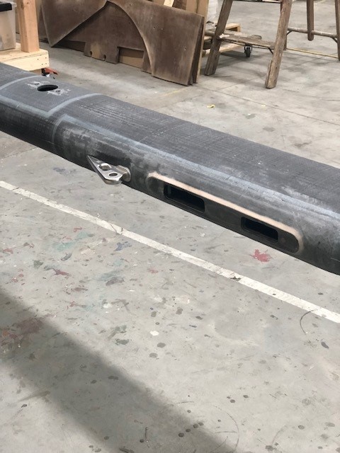
We’re working with Moore Brothers, our skilled team of friends running very cool composite shop in Bristol, RI. These guys have deep skills and experience building some of the more complex composite components seen at the top of industry (and serving multiple industries not just Marine). Moore Bros are the first to say they are not dedicated spar builders, nor do they aim for that market, but when they got wind of our interest in building a spar, their enthusiasm for our project led us all quickly to working together. Using their smart production system and ability to reuse existing tools, we’re able to build a carbon mast and boom with reasonable cost-effectiveness at a reduction of weight that further promotes performance advantages.
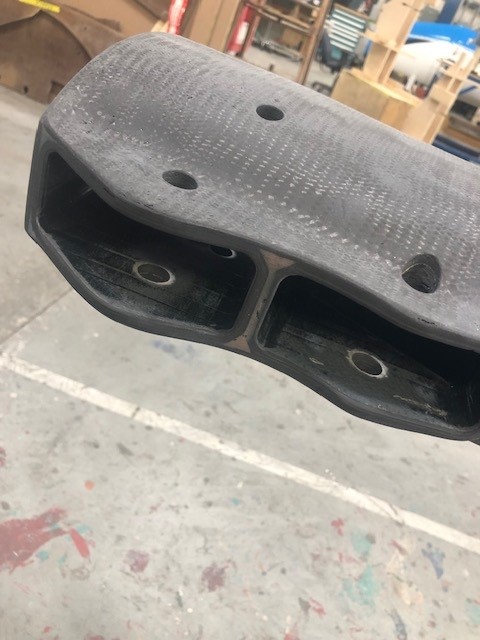
Among the cool tools and tricks that Moore Brothers use to build wild composite parts is a braiding machine. This intimidating-looking contraption looks something like an oversize weaving loom or a medieval torture device. It’s designed to spin strands of composite reinforcement onto a mandrel as the mandrel is passed through its central circle.

The reinforcement can be any fiber or filament – carbon, aramid (Kevlar) or glass – and varying thicknesses of strands. The angle of braiding can be adjusted too, as well as the rate of feed of the mandrel through the machine so a sophisticated system of fiber orientation allows the finished part to be tuned to structural requirements. This is a way to build highly engineered composite parts at a lower cost than hand-laid pre-impregnated sheets.
Because it’s slightly more difficult to apply the rate of resin flow to the fiber matrix as consistently compared with hand-laid prepreg, the strength-to-weight ratio is not quite as high – but the cost reduction can be substantial. For Zingara’s mast, the balance between cost savings and weight savings was a goal– it allowed us to stretch our finances to include carbon spars, and the slight (less than 10 lb) weight penalty over prepreg was acceptable, compared to the triple-digit difference with an aluminum mast.
We also evaluated the cost versus weight of an aluminum boom. Where the vertical center of gravity (VCG) of the boom is so much lower than that of a mast, it’s harder to make a performance-enhancing case for a carbon boom. Besides the slamming weight in a jibe, the chief advantage of a carbon built boom is cosmetic – paint will last longer on a composite boom than on aluminum, when combined with all the dissimilar metals of the fittings.
Each of these tubes will be braided using Moore Brothers’ braiding machine; longitudinal and radial fibers are carbon, with off-axis diagonal fibers being S-glass – a stronger, stiffer variant of glass fibers that approaches carbon in its properties at lower cost.

Moore Brothers has a quiver of mandrels for the various spar sections they can build. The mandrel they’re using for our spar is also used for Class 40 high-performance short-handed racers. It’s a carefully smoothed and faired tapered aluminum extrusion that looks a lot like an aluminum mast. It’s coated with mold release before laminating begins, then is slowly passed through the braiding machine while the machine whirls and spins a web of high-strength fibers. Resin can be carefully painted onto the mandrel by hand, or infused later. The braiding operation can take more than a few hours, depending on the feed rate of the mandrel through the machine. After it’s complete, the laminated tube is placed in an autoclave for high-temperature cure under pressure to eliminate voids.
The braiding process tends to produce a surface that’s more irregular than a hand-laid prepreg system, small amounts of fairing compound and hi-build primers are applied to the spar after curing, and the tube is sanded fair for primer and paint. Following that, the fittings are installed, all pieces are dry-assembled and checked for fit.
Follow the Journey
The journey to transform Zingara provides an excellent opportunity for us to bring a new life to an older beloved boat. It is equal parts passion and practicality. This process illustrates possibilities for other boat owners who wish to consider updates like this and who wish to learn and follow us on this journey. Follow along as we reimagine Zingara and open a world to boat owners who want to do the same.
[embedyt] https://www.youtube.com/watch?v=qqPNYLcY_uE[/embedyt]
Read Similar Stories